QMK USB to USB Keyboard Protocol Converter
17 December 2020
Edited: 11 January 2021
What is this?
The main motivation to build this converter came from this video by Linus Tech Tips where I found out that I can convert almost any USB keyboard into a fully programmable keyboard using QMK firmware.
QMK Firmware
![]()
After spending some time on /r/mechanicalkeyboards and /r/olkb I found out that custom mechanical keyboards are typically programmable via QMK firmware.
Your computer keyboard has a processor inside of it, similar to the one inside your computer. This processor runs software that is responsible for detecting button presses and informing the computer when keys are pressed. QMK Firmware fills the role of that software, detecting button presses and passing that information on to the host computer. When you build your custom keymap, you are creating an executable program for your keyboard.
So QMK allows me to program a keyboard by adding custom functionality (keymaps and macros, etc), and that is good news.
Unfortunately, most off-the-shelf keyboards do not come with a programmable firmware (like my keyboard). What can I do to reprogram it?
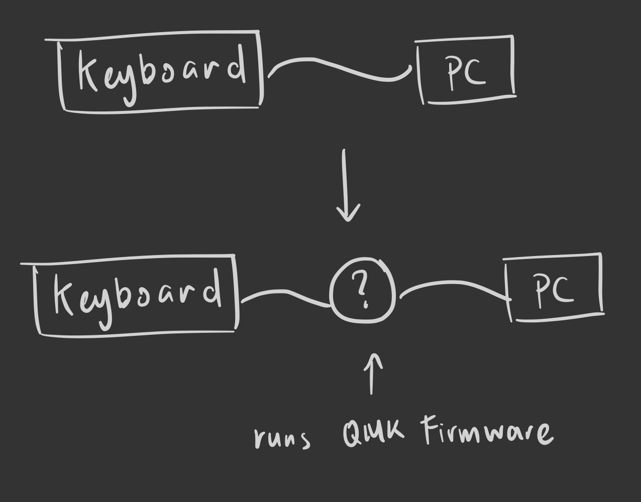
USB to USB Converter
To reprogram a “dumb” keyboard we need to connect it to a converter, where the converter is loaded with QMK Firmware.
Well, turns out there is already such implementation out there (Hasu’s USB to USB converter), but it is too expensive for me.
Here are some reviews on Hasu’s implementation:
DIY USB to USB Converter
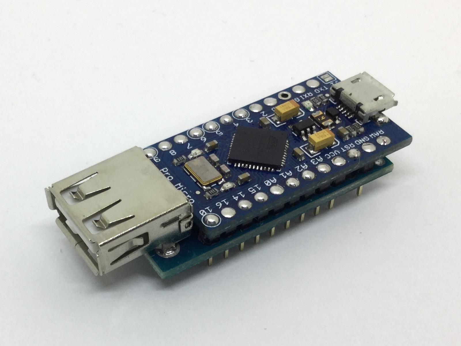
Digging further, I found out that there is a way to DIY the converter with just:
- Pro Micro (3.3v/8MHz)
- 3.3v USB Mini Host Shield
- Soldering skills
geekhack - USB to USB keyboard converter build log(Pro Micro 3.3v with mini host shield)
A rough idea of how it works is that a USB host controller chip (MAX3421E) will communicate with an AVR microcontroller (ATMega32U4) via SPI.
Limitations
Before we get to building it, there are some minor limitations to the USB converter.
The limitations of the USB converter includes:
- 6KRO (because it operates in HID USB boot protocol mode)
- it is possible to get NKRO, but we would have to write our own HID report
- Media/System control keys and
Fnkeys are not recognized - Max firmware size of ~28KB (will affect how much custom code you can write)
- booloader is around 4KB and the ATMega32U4 has rougly 32KB of programmable memory
Research on 6KRO/NKRO/Ghosting
Here are some information regarding the different operating modes of a typical/gaming keyboard.
1: 6KRO (Boot Protocol)
To avoid complexity in simpler USB stacks (e.g. BIOS, bootloaders and KVM switches), the USB HID standard specifies that keyboards and mice can declare themselves to be “boot-capable” (source).
The HID USB boot protocol operates in 6KRO which imposes a limit of six concurrent keys plus modifiers:
- 4 pairs of modifiers (Shift, Control, Alt and Windows/Command)
- 6 arbitrarily chosen keys
2: Ghosting
To get to NKRO, we need to first prevent ghosting which can occur in the keyboard’s matrix.
Here are a few good examples explaining how does ghosting happen and how to prevent it (using diodes).
- http://pcbheaven.com/wikipages/How_Key_Matrices_Works/
- https://deskthority.net/wiki/Rollover,_blocking_and_ghosting#A_technical_explanation_of_NKRO
- https://beta.docs.qmk.fm/developing-qmk/for-a-deeper-understanding/how_keyboards_work
The general idea is to use a diode (like 1N148) which allows for the flow of current in one direction. The reason behind this is that a microcontroller only has a limited number of inputs which does not match the 70++ keys that a keyboard might have.
Reading more on building hand-wired keyboards will allow you to understand more of how the keyboard matrix is done.
3: NKRO
NKRO is still unfamiliar for me and as of now, it seems like the the HID report descriptor is used to enable NKRO.
TODO: Read up on NKRO
Wiring Guide
These are the guides I followed to solder the Pro Micro to the Mini USB Host Shield:
⚠️ It is important to cut the VBUS line ⚠️
Wiring Guide: Cutting VBUS line
An important thing to do before soldering the 2 boards together is to cut the VBUS line on the USB Host Shield.
This has to be done because the the USB Host Shield (MAX3421E) operates in 3.3v while the USB Bus Voltage operates in 5V (which supplies power to the USB device).
Not cutting the VBUS may damage the MAX3421E chip.
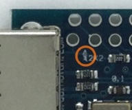
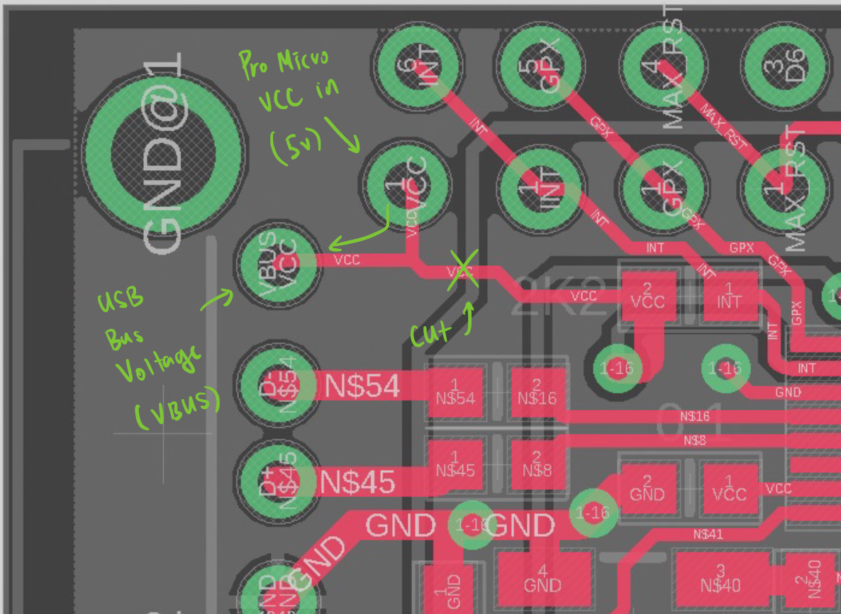
As we can see, VCC is the where the RAW (5v) is connected.
If the circuit is not cut, the keyboard AND the MAX3421E chip will be receiving 5V.
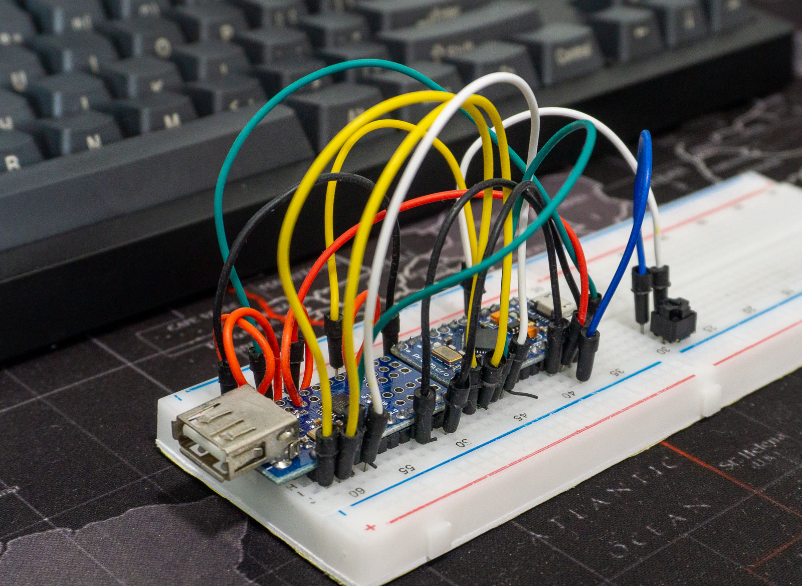
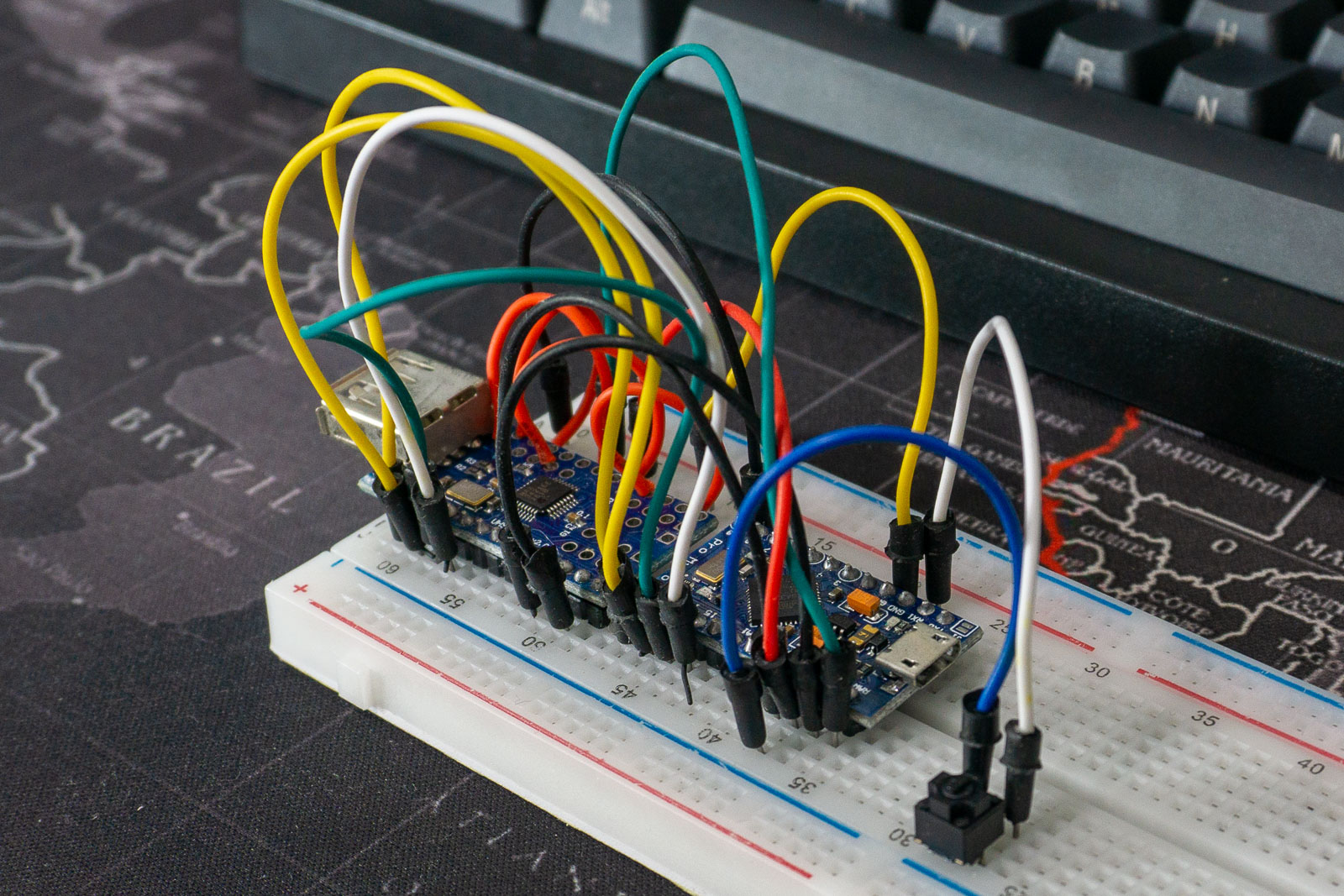
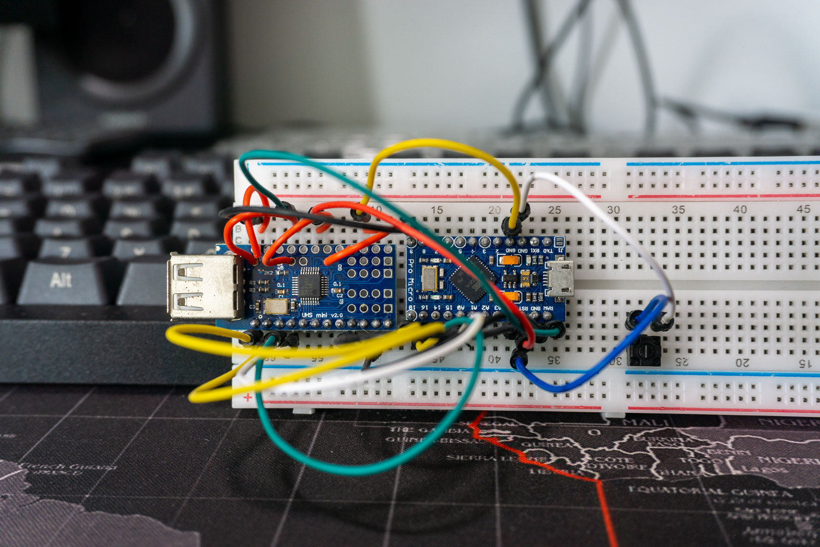
Prototype
The required items for building one such device:
- Pro Micro ATMega32U4 3.3V (AliExpress, ~ $5 SGD)
- Mini USB Host Shield (AliExpress, ~ $5 SGD)
- Breadboard (for prototyping)
- Switch (I desoldered an OMRON switch from an old mouse)
Here is the prototype that I have attempted before soldering the 2 devices together:
Flashing QMK
To flash QMK onto the Pro Micro, I used AVRDUDESS.
I have tried using QMK Toolbox however, it is unable to detect the Pro Micro.
Flasing: Compiling QMK Firmware
- Go to https://config.qmk.fm/ to configure your keymap first
- Download the
keymap.jsonfile - Run command to generate the keymap
qmk compile your_keymap.json- If you need to recompile after adjusting the
rules.mkfile, just doqmk compile -kb converter/usb_usb/pro_micro -km your_keymap
- If you need to recompile after adjusting the
- Your compiled
.hexfile will be under$QMK_DIR/.buildfolder - Flash
.hexfile using AVRDUDESS
Flashing: Reducing Firmware Size (Extra)
When compiling, if you ever see a message like this
Linking: .build/converter_usb_usb_pro_micro_yaowei_config_ansi_v3.elf                               [OK]
Creating load file for flashing: .build/converter_usb_usb_pro_micro_yaowei_config_ansi_v3.hex       [OK]
Copying converter_usb_usb_pro_micro_yaowei_config_ansi_v3.hex to qmk_firmware folder                [OK]
Checking file size of converter_usb_usb_pro_micro_yaowei_config_ansi_v3.hex
 * The firmware is too large! 35532/28672 (6860 bytes over)
 [ERRORS]

make[1]: *** [tmk_core/rules.mk:417: check-size] Error 1
Make finished with errors
make: *** [Makefile:584: converter/usb_usb/pro_micro:yaowei_config_ansi_v3] Error 1
This means that the QMK program exceeded the maximum flashable size that a Pro Micro have.
A Pro Micro uses a ATmega32U4 microcontroller which as 32KB of flashable memory and 2KB is for the bootloader.
To reduce the file size, you may want to enable Link Time Optimization (disables Macros and Functions) or disable features via the rules.mk file.
# Enable Link Time Optimization
# Macro and Function features are incompatible with LTO
EXTRAFLAGS += -flto
For more tips, checkout Thomas Baart’s guide!
https://thomasbaart.nl/2018/12/01/reducing-firmware-size-in-qmk/
Enclosure Design
After the prototyping is successful, I want to have a case/enclosure for the final product.
I decided to create a 3D printed enclosure for the converter using Fusion 360 since I have an education license.
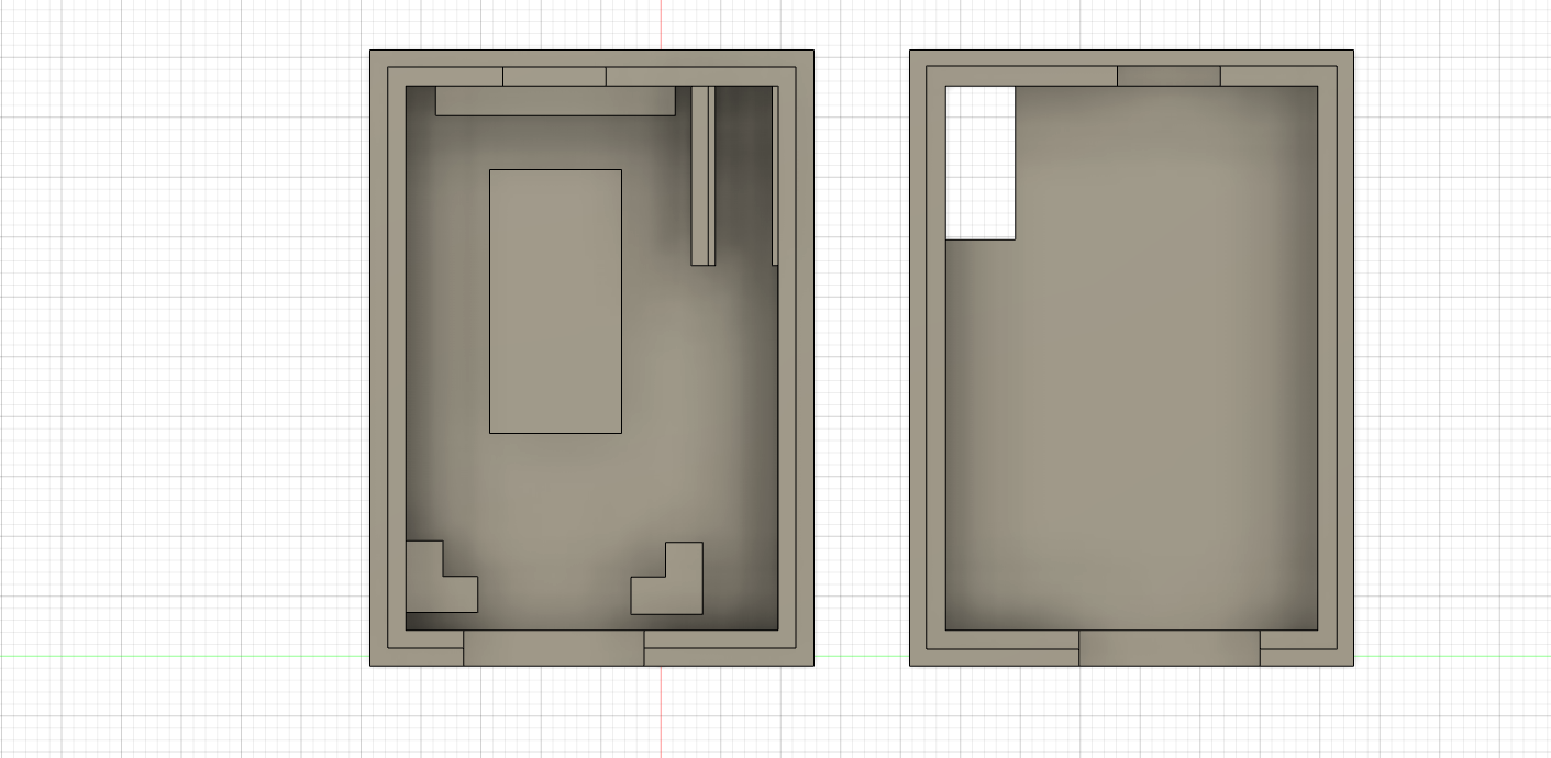
Design 1
Version 1 of the design took 2 days to complete since I had to learn Fusion 360.
After printing it, I realised that the dimensions were a little too tight for the switch and the USB Host Shield. Furthermore, I did not think of how to attach the top and bottom part of the case together.
This prompted a redesign.
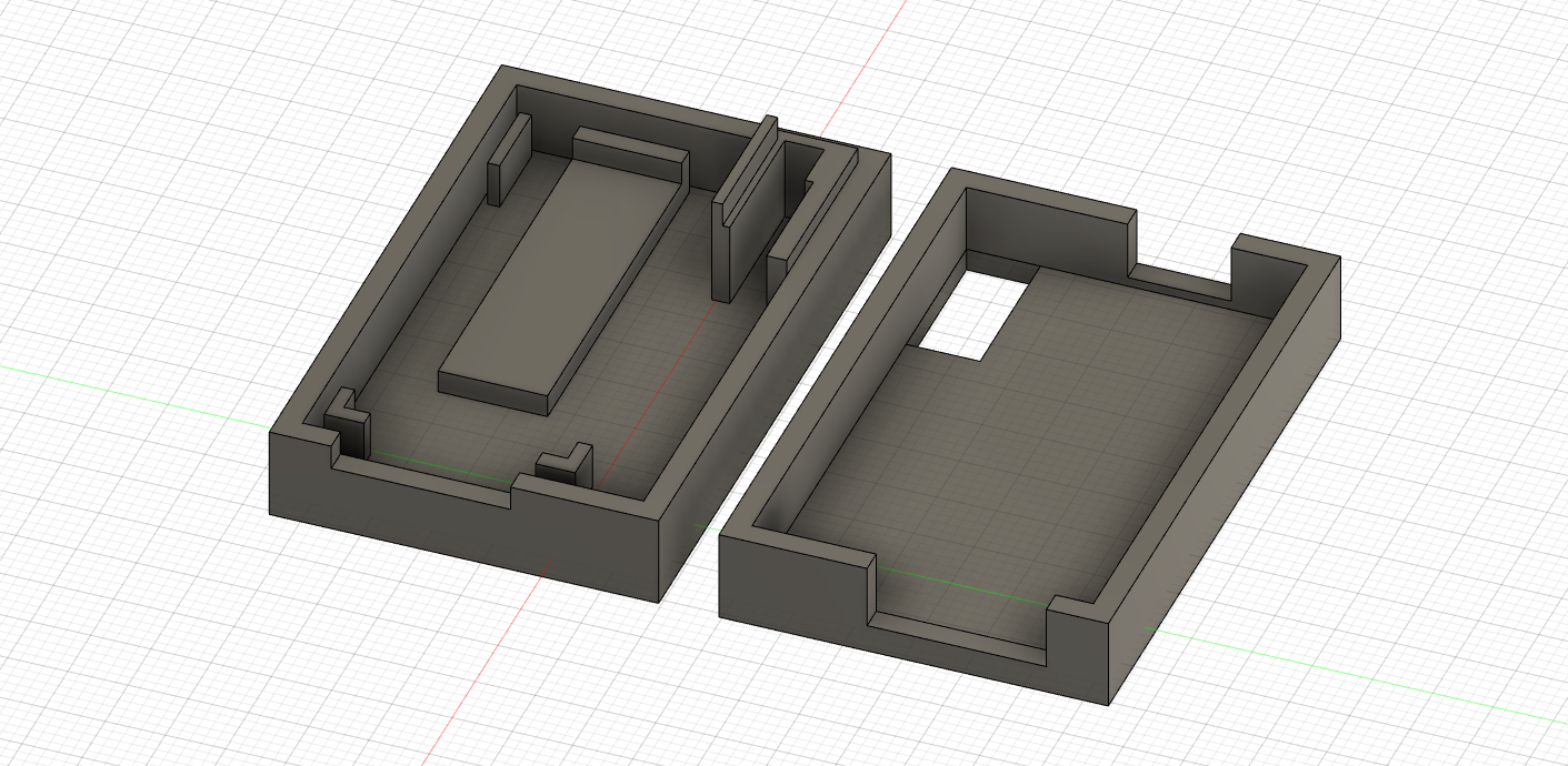
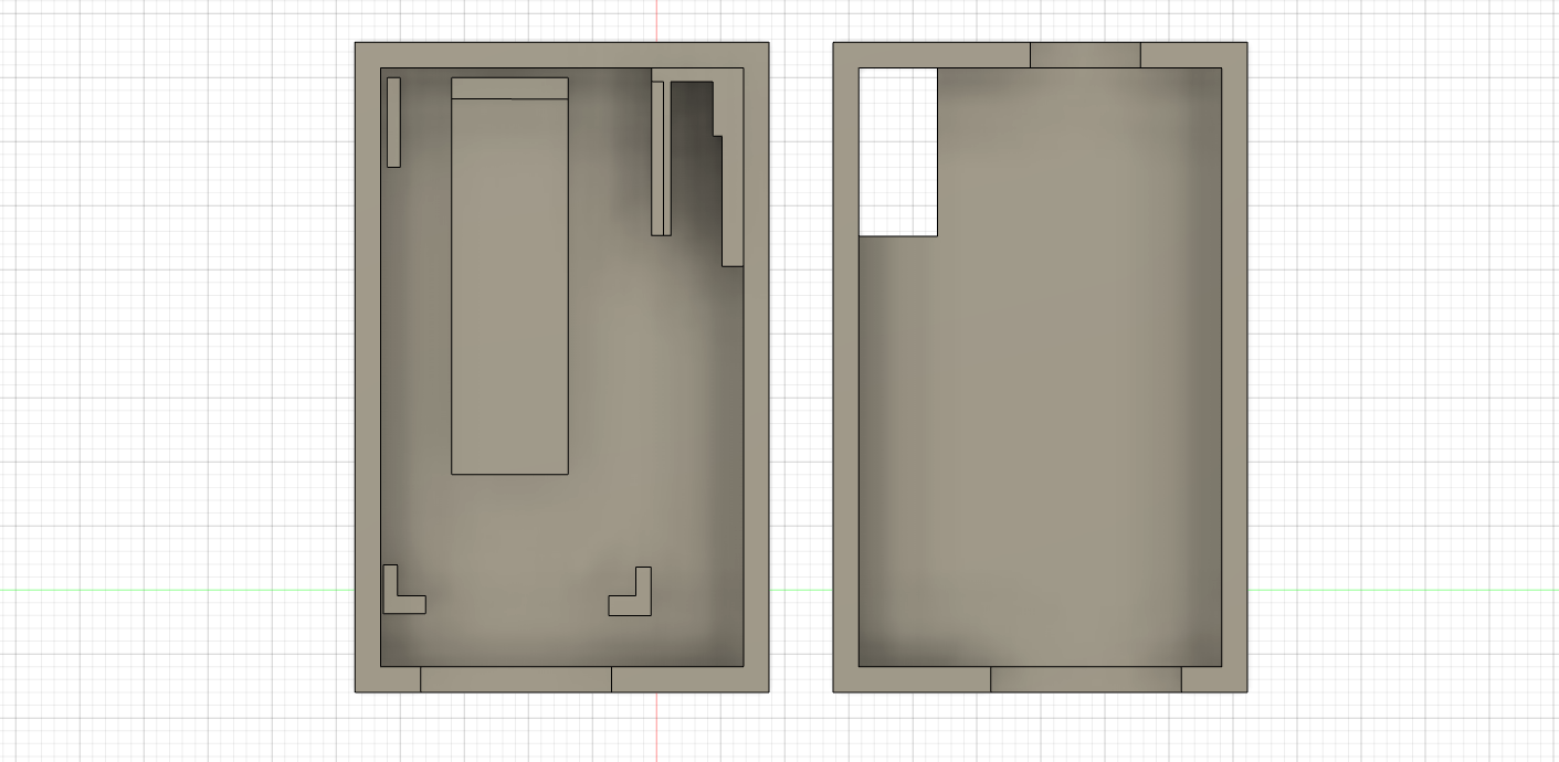
Design 2
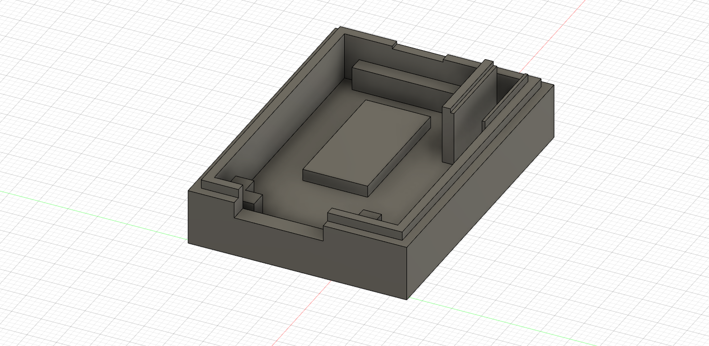
For the second design, I initially planned to leave a 0.1mm gap and afterwards use acrylic glue to secure both sides together. However, after printing the case, the rough edges of the print allowed me to have a semi secure fit without using glue.
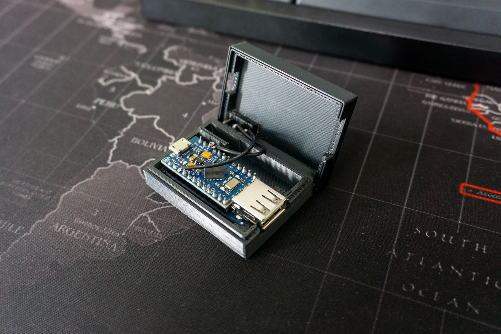
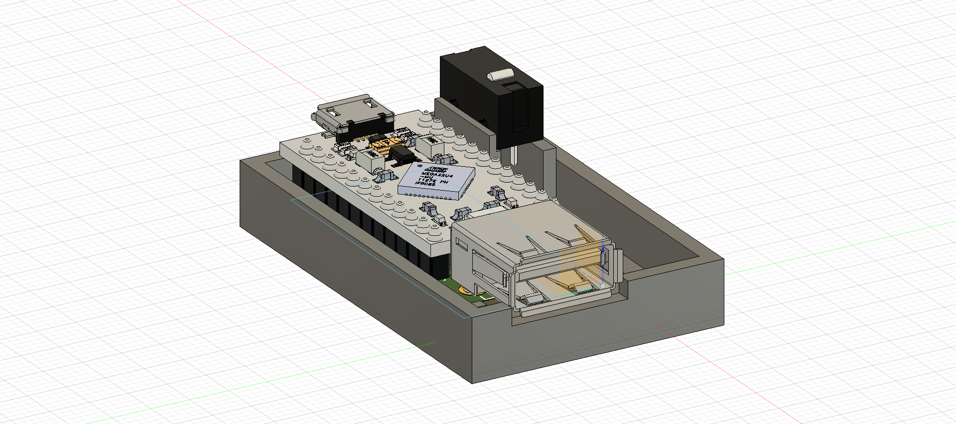
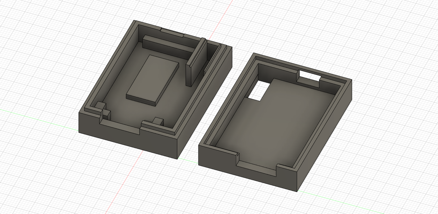
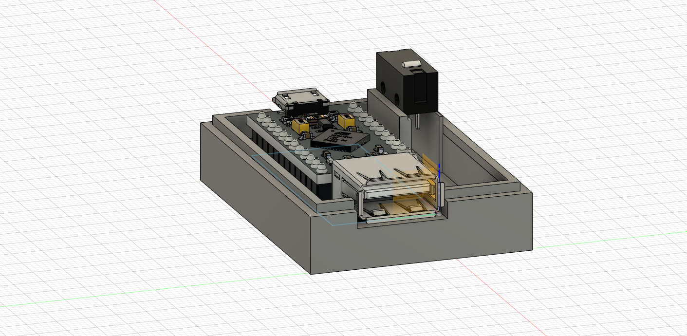
Final (Design 2)
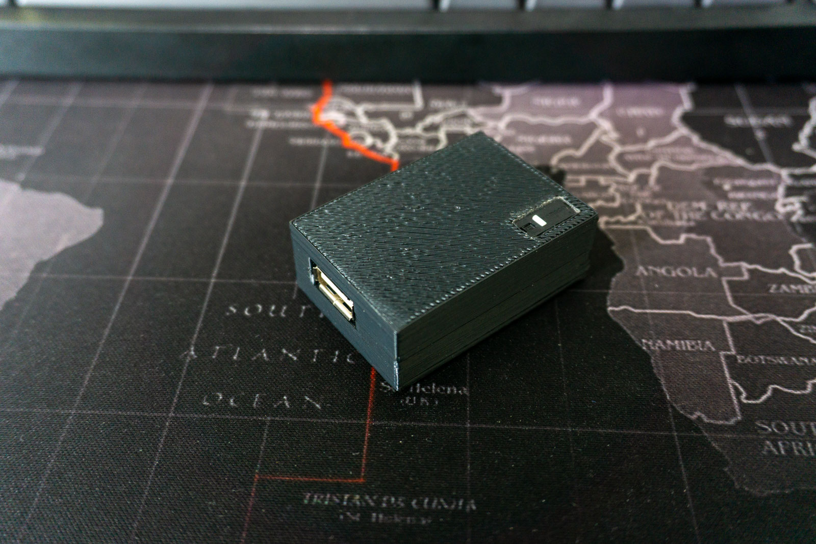
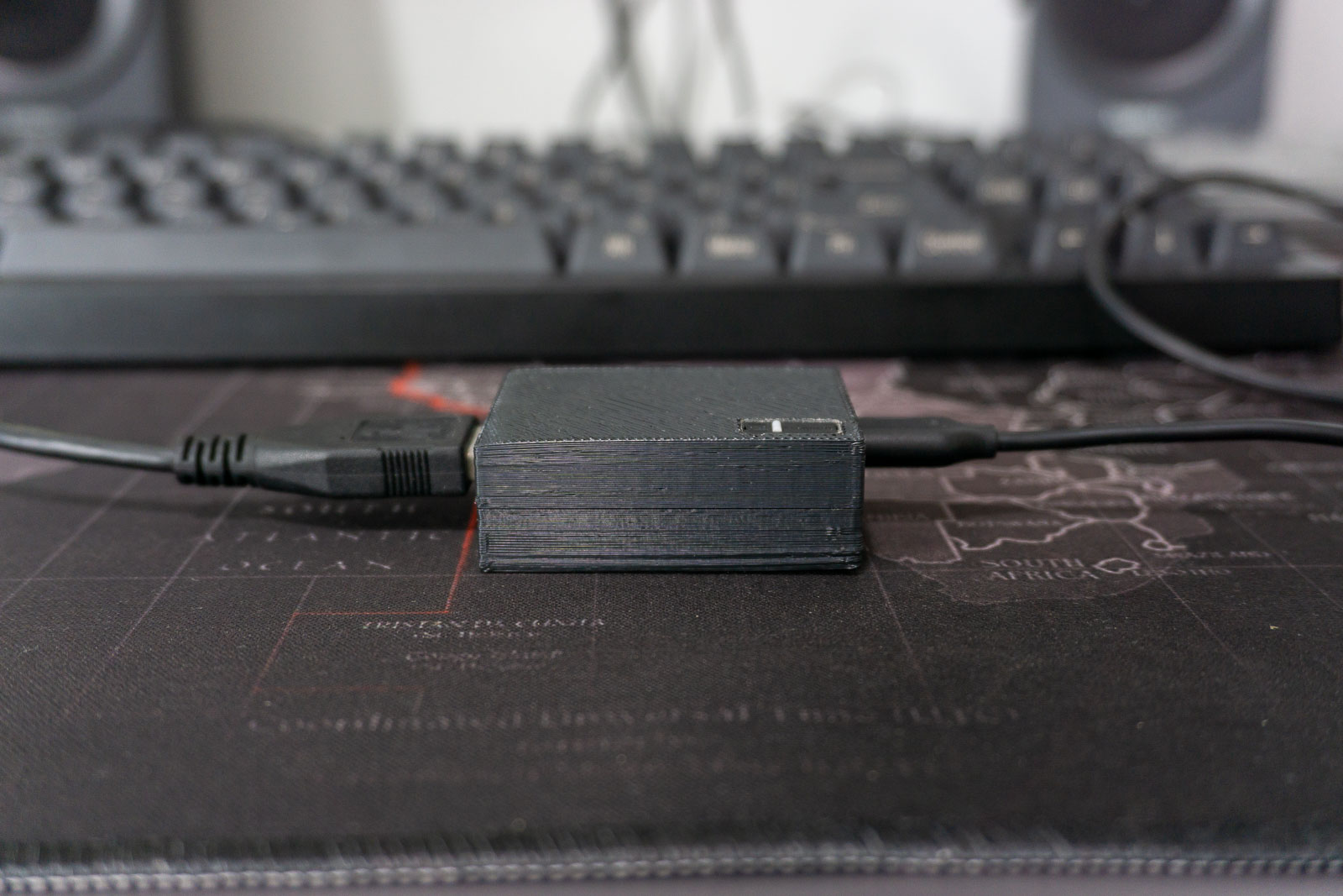
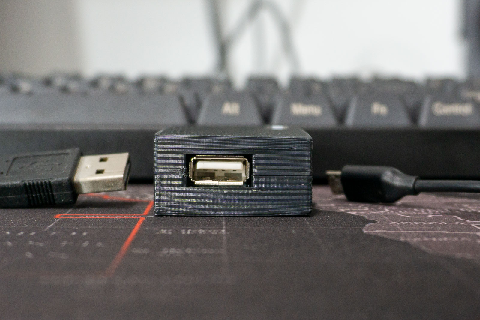
The USB Mini port hole could be further adjusted to accept wider USB cables.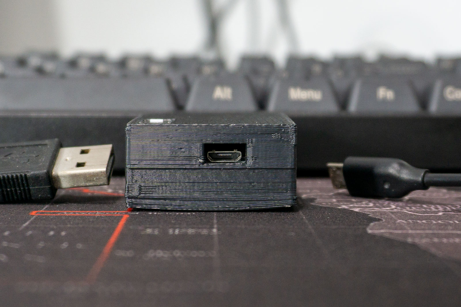
Of course here are some failed prints.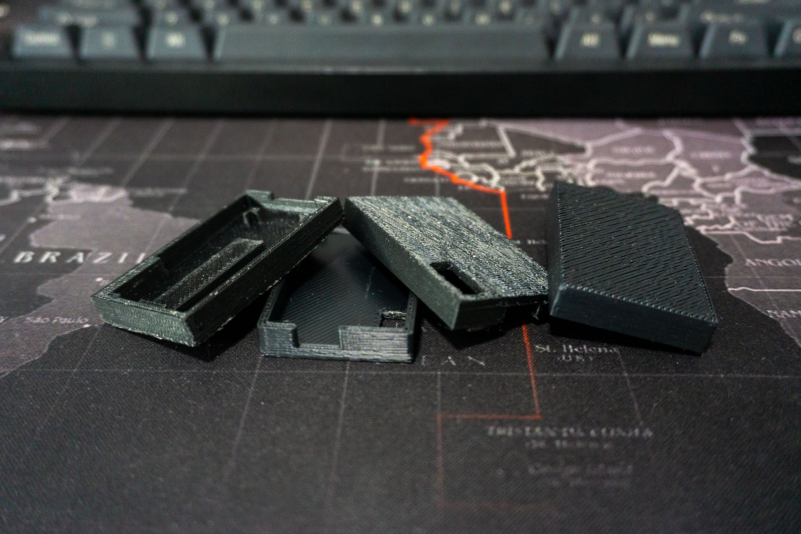
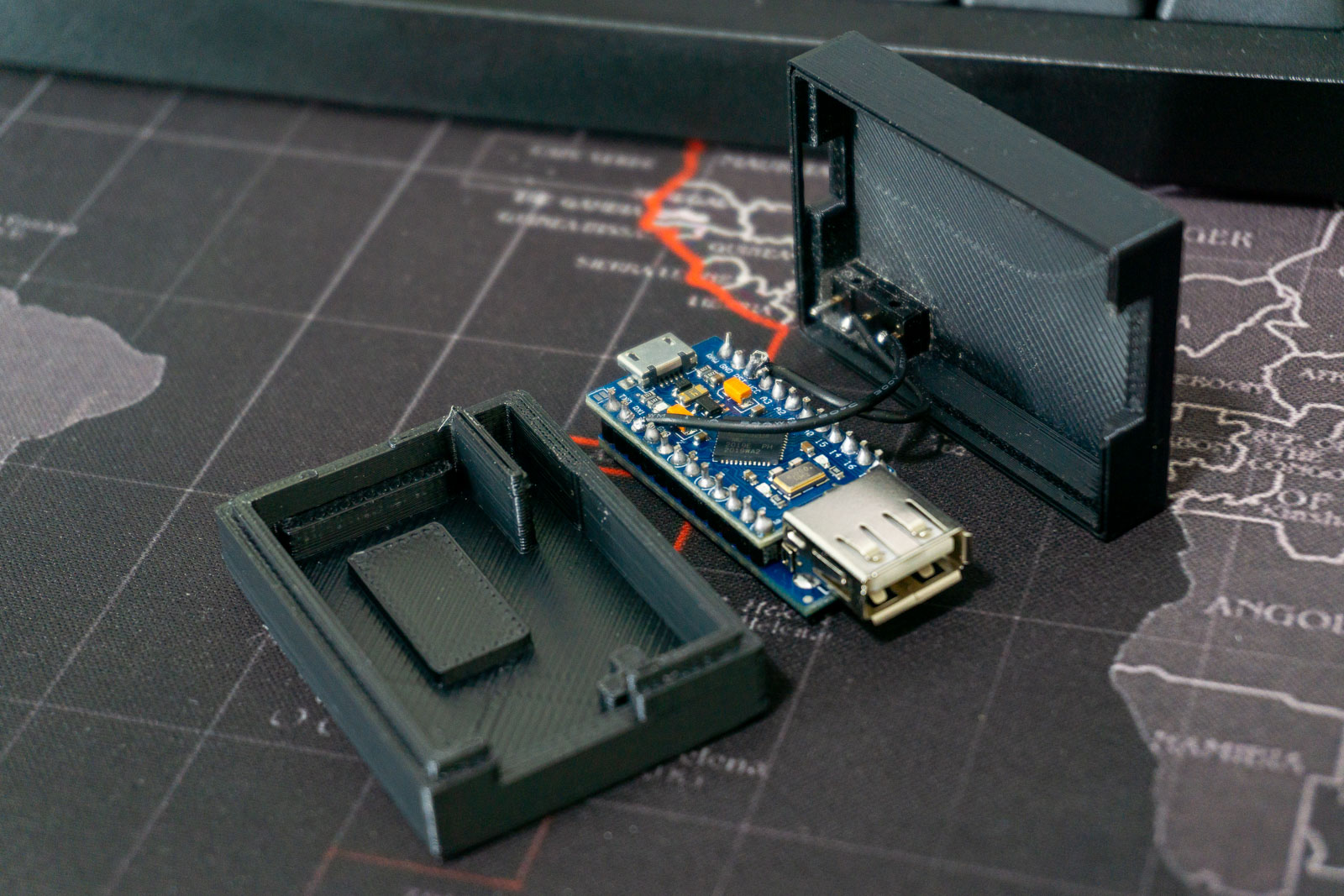
My Thoughts
While the final enclosure that I ended up with isn’t perfect, it works well enough for now.
Here are some of the issues with the current design which I plan to fix soon:
- The USB Host Shield board isn’t glued onto the bottom case and thus can shift around when plugging in the USB Mini cable.
- 3D printer isn’t able to print a very thin wall (around 0.2mm) which led to one part of the design not printing (might want to remove the wall)
- 3D printer causes enclosure to warp (might need to keep printing until I get a proper case)
Overall, I’m pretty satisfied with the end product.
My QMK Configuration
Here is my current basic setup that allows me to use it with a 65% and 87% keyboard with VIM like arrow layer when caps lock is held down.
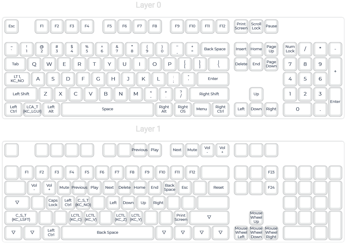
View my configuration file here:
If you are interested, there are some great keymaps that others have contributed in QMK’s repository https://github.com/qmk/qmk_firmware/tree/master/keyboards/converter/usb_usb/keymaps